Dell™ Dimension™ 9150 Service Manual
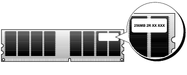
You can increase your computer memory by installing memory modules on the system board. For information on the type of memory supported by your computer, see "Specifications."

|
NOTICE: Before you install new memory modules, download the most recent BIOS for your computer from the Dell™ Support website at support.dell.com. |

|
NOTE: Always install memory modules in the order indicated on the system board. |
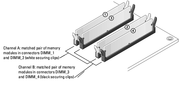
The recommended memory configurations are:
or
|
|
NOTICE: Do not install ECC or buffered memory modules. Only unbuffered, non-ECC memory is supported. |
|
|
NOTE: Memory purchased from Dell is covered under your computer warranty. |
|
|
NOTICE: If you remove your original memory modules from the computer during a memory upgrade, keep them separate from any new modules that you may have, even if you purchased the new modules from Dell. If possible, do not pair an original memory module with a new memory module. Otherwise, your computer may not start properly. You should install your original memory modules in pairs either in connectors DIMM_1 and DIMM_2 or connectors DIMM_3 and DIMM_4. |
Your computer supports a maximum of 4 GB of memory when you use four 1-GB DIMMs. Current operating systems, such as Microsoft® Windows® XP, can only use a maximum of 4 GB of address space; however, the amount of memory available to the operating system is less than 4 GB. Certain components within the computer require address space in the 4-GB range. Any address space reserved for these components cannot be used by computer memory.

|
CAUTION: Before you begin any of the procedures in this section, follow the safety instructions in the Product Information Guide. |
|
|
NOTICE: To prevent static damage to components inside your computer, discharge static electricity from your body before you touch any of your computer's electronic components. You can do so by touching an unpainted metal surface on the computer. |
|
|
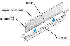
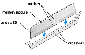
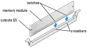
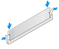
NOTICE: To avoid damage to the memory module, press the module straight down into the connector while you apply equal force to each end of the module. |
If you insert the module correctly, the securing clips snap into the cutouts at each end of the module.
|
|
NOTICE: To connect a network cable, first plug the cable into the network port or device and then plug it into the computer. |
|
|
CAUTION: Before you begin any of the procedures in this section, follow the safety instructions in the Product Information Guide. |
|
|
NOTICE: To prevent static damage to components inside your computer, discharge static electricity from your body before you touch any of your computer's electronic components. You can do so by touching an unpainted metal surface on the computer. |
If the module is difficult to remove, gently ease the module back and forth to remove it from the connector.
|
|
CAUTION: Before you begin any of the procedures in this section, follow the safety instructions in the Product Information Guide. |
|
|
NOTICE: To prevent static damage to components inside your computer, discharge static electricity from your body before you touch any of your computer's electronic components. You can do so by touching an unpainted metal surface on the computer. |
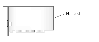
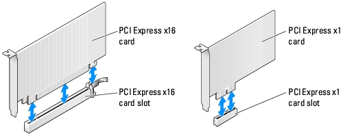
Your Dell™ computer provides the following slots for PCI and PCI Express cards:
|
|
NOTE: Dell offers an optional customer kit for Audigy II and IEEE 1394 PCI add-in-cards that includes a front-mounted IEEE 1394 connector. |
|
|
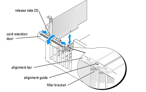
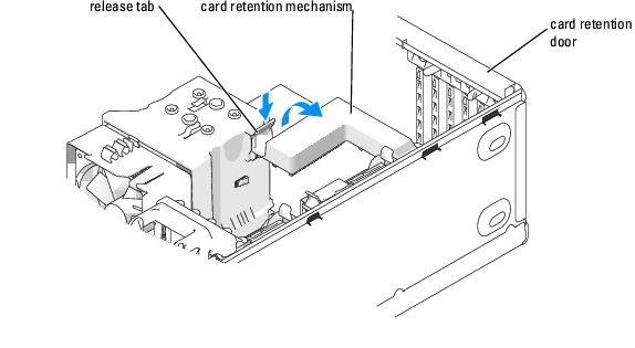
NOTE: Installing filler brackets over empty card-slot openings is necessary to maintain FCC certification of the computer. The brackets also keep dust and dirt out of your computer. |
See the documentation that came with the card for information on configuring the card, making internal connections, or otherwise customizing it for your computer.
|
|
CAUTION: Some network adapters automatically start the computer when they are connected to a network. To guard against electrical shock, be sure to unplug your computer from its electrical outlet before installing any cards. |
|
|
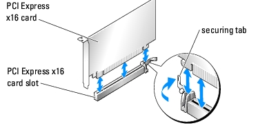
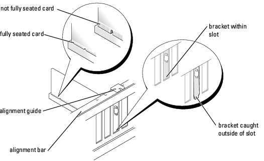
NOTICE: Ensure that you release the securing tab to seat the card. If the card is not installed correctly, you may damage the system board. |
|
|
NOTICE: Do not route card cables over or behind the cards. Cables routed over the cards can prevent the computer cover from closing properly or cause damage to the equipment. |
See the documentation for the card for information about the card cable connections.
|
|
NOTICE: To connect a network cable, first plug the cable into the network port or device and then plug the cable into the computer. |
If you installed a sound card:
If you removed a sound card:
If you installed an add-in network adapter and want to disable the integrated network adapter:
If you removed an add-in network connector:
|
|
CAUTION: Before you begin any of the procedures in this section, follow the safety instructions in the Product Information Guide. |
|
|
CAUTION: To guard against electrical shock, always unplug your computer from the electrical outlet before removing the cover. |
|
|
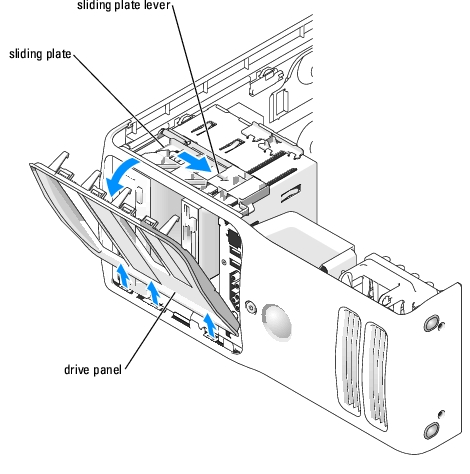
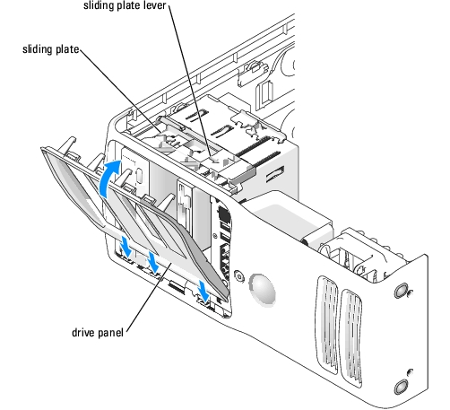
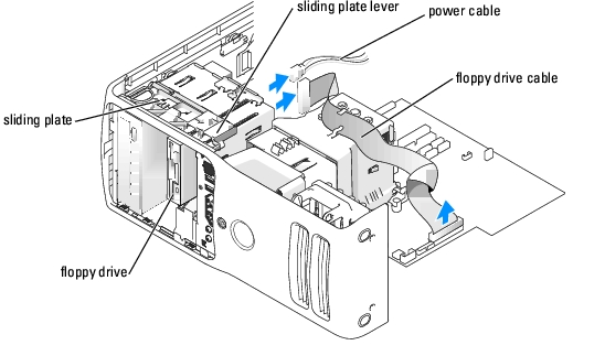
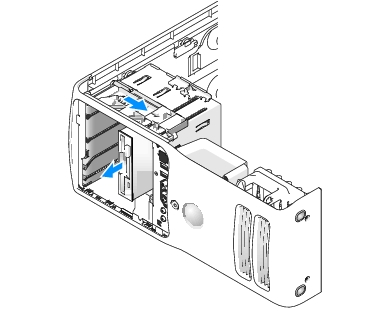
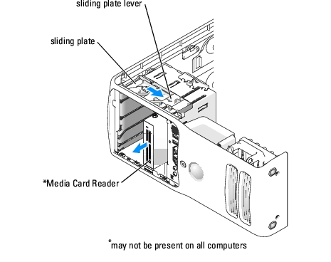
NOTE: The sliding plate secures and releases the drive panel and helps to secure the drives. |
|
|
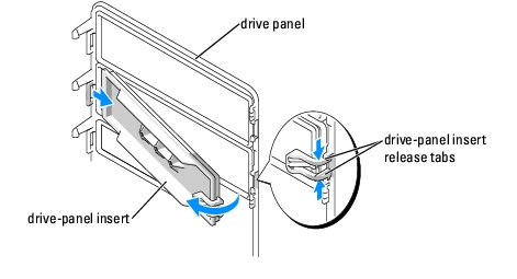
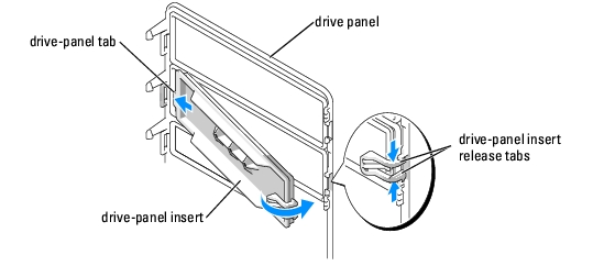
NOTICE: Drive-panel inserts may contain screws on the inside. You can attach the screws to new drives that do not have any screws. |
|
|
NOTICE: To avoid breaking the drive-panel insert tab, do not pull the insert more than approximately 1 cm (½ inch) away from the drive panel before sliding the tab out of the slot. |
Your computer supports:
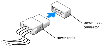
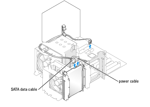
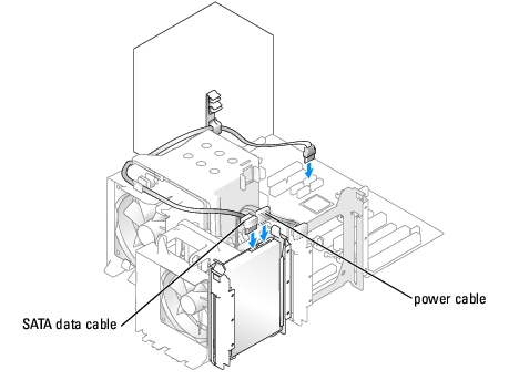
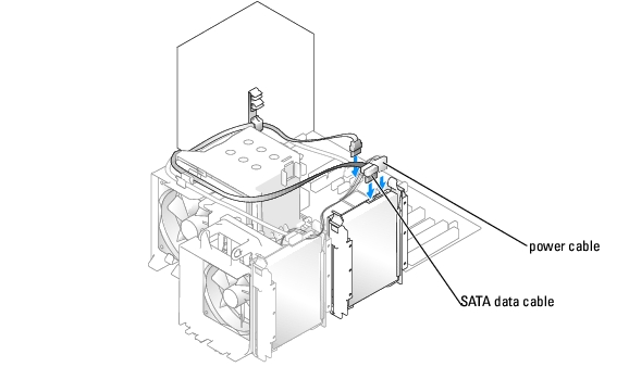
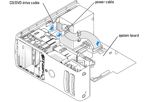
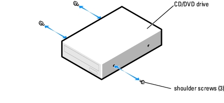
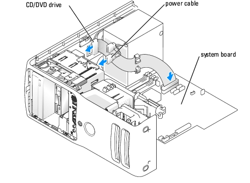
When you install a drive, you connect two cables—a DC power cable and a data cable—to the back of the drive and to the system board. Some CD/DVD drives may also have an audio connector; one end of the audio cable will attach to the drive connector and the other will attach to the system board.
Connect hard drives to data connectors labeled "SATA" and connect CD/DVD drives to connectors labeled "IDE".
When you connect two IDE devices to a single IDE interface cable and configure them for the cable select setting, the device attached to the last connector on the interface cable is primary or the boot device (drive 0), and the device attached to the middle connector on the interface cable is the secondary device (drive 1). See the drive documentation in your upgrade kit for information on configuring devices for the cable select setting.
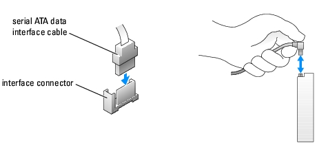
Most interface connectors are keyed for correct insertion; that is, a notch or a missing pin on one connector matches a tab or a filled-in hole on the other connector. Keyed connectors ensure that the pin-1 wire in the cable (indicated by the colored stripe along one edge of the IDE cable—serial ATA cables do not use a colored stripe) goes to the pin-1 end of the connector. The pin-1 end of a connector on a board or a card is usually indicated by a silk-screened "1" printed directly on the board or card.
|
|
NOTICE: When you connect an IDE interface cable, do not place the colored stripe away from pin 1 of the connector. Reversing the cable prevents the drive from operating and could damage the controller, the drive, or both. |
When connecting an IDE cable, ensure that you align the colored stripe with the pin 1 connector. When disconnecting an IDE cable, grasp the colored pull tab and pull until the connector detaches.
When connecting and disconnecting a serial ATA cable, hold the cable by the connector at each end. Like IDE connectors, the serial ATA interface connectors are keyed for correct insertion; that is, a notch or a missing pin on one connector matches a tab or a filled-in hole on the other connector.
|
|
CAUTION: Before you begin any of the procedures in this section, follow the safety instructions in the Product Information Guide. |
|
|
CAUTION: To guard against electrical shock, always unplug your computer from the electrical outlet before opening the cover. |
|
|
NOTICE: To avoid damage to the drive, do not set it on a hard surface. Instead, set the drive on a surface, such as a foam pad, that will sufficiently cushion it. |
|
|
NOTICE: To connect a network cable, first plug the cable in to the network port or device and then plug the cable in to the computer. |
See the documentation that came with the hard drive for instructions about installing any software required for the operation of the hard drive.
See the documentation for your operating system for instructions.
|
|
CAUTION: Before you begin any of the procedures in this section, follow the safety instructions in the Product Information Guide. |
|
|
CAUTION: To guard against electrical shock, always unplug your computer from the electrical outlet before opening the cover. |
|
|
NOTICE: To avoid damage to the drive, do not set it on a hard surface. Instead, set the drive on a surface, such as a foam pad, that will sufficiently cushion it. |
|
|
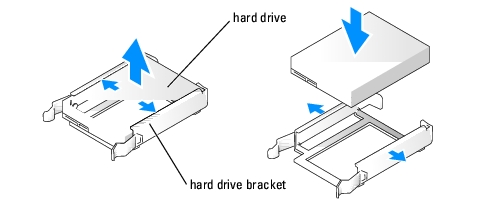
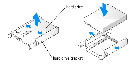
NOTICE: Do not install any drive into the lower hard-drive bay until you have removed the hard drive bracket from the inside of the hard drive bay. |
|
|
NOTE: If your replacement hard drive does not have the hard drive bracket attached, remove the bracket from the old hard drive by unsnapping it from the drive. Snap the bracket onto the new hard drive. |
|
|
NOTICE: To connect a network cable, first plug the cable into the network port or device and then plug it into the computer. |
See the documentation that came with the drive for instructions on installing any software required for drive operation.
|
|
CAUTION: Before you begin any of the procedures in this section, follow the safety instructions in the Product Information Guide. |
|
|
CAUTION: To guard against electrical shock, always unplug your computer from the electrical outlet before opening the cover. |
|
|
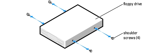
NOTE: If you are adding a floppy drive, see "Installing a Floppy Drive." |
|
|
NOTICE: To connect a network cable, first plug the cable in to the network port or device and then plug it in to the computer. |
See the documentation that came with the floppy drive for instructions on installing any software required for the operation of the drive.
|
|
CAUTION: Before you begin any of the procedures in this section, follow the safety instructions in the Product Information Guide. |
|
|
NOTICE: To prevent static damage to components inside your computer, discharge static electricity from your body before you touch any of your computer's electronic components. You can do so by touching an unpainted metal surface on the computer chassis. |
|
|
CAUTION: Before you begin any of the procedures in this section, follow the safety instructions in the Product Information Guide. |
|
|
NOTICE: To prevent static damage to components inside your computer, discharge static electricity from your body before you touch any of your computer's electronic components. You can do so by touching an unpainted metal surface on the computer chassis. |
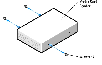
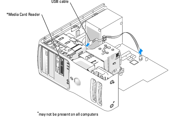
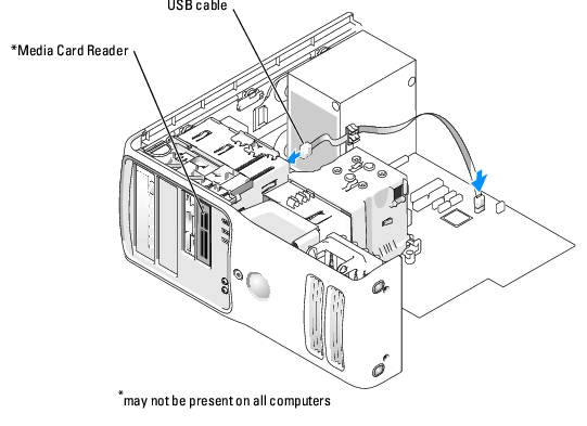
Ensure that the Media Card Reader is installed before the FlexBay cable is connected.
|
|
CAUTION: Before you begin any of the procedures in this section, follow the safety instructions in the Product Information Guide. |
|
|
CAUTION: To guard against electrical shock, always unplug your computer from the electrical outlet before opening the cover. |
Check the documentation that accompanied the drive to verify that the drive is configured for your computer. If you are installing an IDE drive, configure the drive for the cable select setting.
|
|
NOTICE: To connect a network cable, first plug the cable in to the network port or device and then plug it in to the computer. |
See the documentation that came with the drive for instructions on installing any software required for drive operation.
|
|
CAUTION: Before you begin any of the procedures in this section, follow the safety instructions in the Product Information Guide. |
Note the routing of the DC power cables underneath the tabs in the computer frame as you remove them from the system board and drives. You must route these cables properly when you replace them to prevent them from being pinched or crimped.
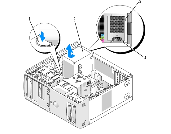
1 release button 2 power supply 3 screws (4) 4 AC power connector
|
|
CAUTION: Before you begin any of the procedures in this section, follow the safety instructions in the Product Information Guide. |
|
|
NOTICE: To connect a network cable, first plug the cable into the network port or device and then plug the cable into the computer. |
|
|
CAUTION: Before you begin any of the procedures in this section, follow the safety instructions in the Product Information Guide. |

|
|
CAUTION: Despite having a plastic shield, the heat-sink assembly may be very hot during normal operation. Be sure that it has had sufficient time to cool before you touch it. |
|
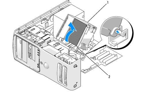
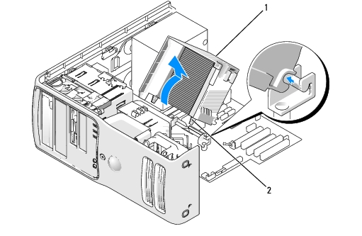
1 |
heat sink and fan shroud assembly |
|
2 |
captive screw housing (2) |
|
|
NOTICE: If you are installing a processor upgrade kit from Dell, discard the original heat sink. If you are not installing a processor upgrade kit from Dell, reuse the original heat sink when you install your new processor. |
|
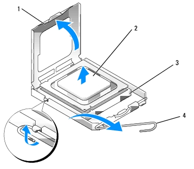
1 |
processor cover |
|
2 |
processor |
|
3 |
socket |
|
4 |
release lever |
|
|
NOTICE: When the release lever is freed, the processor may shift in place. Before securing the processor cover after it has been opened, ensure that the notches on the processor are aligned with the notches on the socket. |
|
|
NOTICE: When replacing the processor, do not touch any of the pins inside the socket or allow any objects to fall on the pins in the socket. |
Leave the release lever extended in the release position so that the socket is ready for the new processor.
|
|
NOTICE: Ground yourself by touching an unpainted metal surface on the back of the computer. |
|
|
NOTICE: When replacing the processor, do not touch any of the pins inside the socket or allow any objects to fall on the pins in the socket. |
|
|
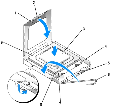
NOTICE: You must position the processor correctly in the socket to avoid permanent damage to the processor and the computer when you turn on the computer. |
|
1 |
processor cover |
6 |
release lever |
|
2 |
securing tab |
7 |
front alignment notch |
|
3 |
processor |
8 |
socket and processor pin-1 indicator |
|
4 |
processor socket |
9 |
rear alignment notch |
|
5 |
center cover latch |
|
|
|
|
NOTICE: To avoid damage, ensure that the processor aligns properly with the socket, and do not use excessive force when you install the processor. |
Ensure that the securing tab on the processor cover is positioned underneath the center cover latch on the socket.
|
|
NOTICE: If you are not installing a processor upgrade kit from Dell, reuse the original heat-sink assembly when you replace the processor. |
If you installed a processor replacement kit from Dell, return the original heat-sink assembly and processor to Dell in the same package in which your replacement kit was sent.
|
|
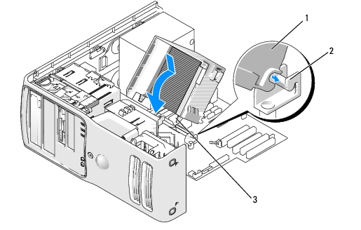
NOTICE: Ensure that the heat sink is correctly seated and secure. |
|
1 |
heat sink and fan shroud assembly |
|
2 |
heat-sink assembly bracket |
|
3 |
captive screw housing (2) |
|
|
NOTICE: To connect a network cable, first plug the cable into the network port or device and then plug the cable into the computer. |
|
|
CAUTION: Before you begin any of the procedures in this section, follow the safety instructions in the Product Information Guide. |
|
|
CAUTION: To guard against electrical shock, always unplug your computer from the electrical outlet before opening the cover. |
|
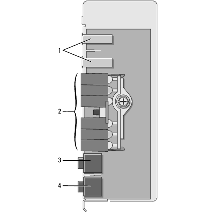
1 |
USB ports |
|
2 |
diagnostic, hard-drive activity, and network lights |
|
3 |
headphones connector |
|
4 |
microphone connector |
|
|
CAUTION: Despite having a plastic shield, the heat-sink assembly may be very hot during normal operation. Be sure that it has had sufficient time to cool before you touch it. |
|
1 |
heat sink and fan shroud assembly |
|
2 |
captive screw housing (2) |
|
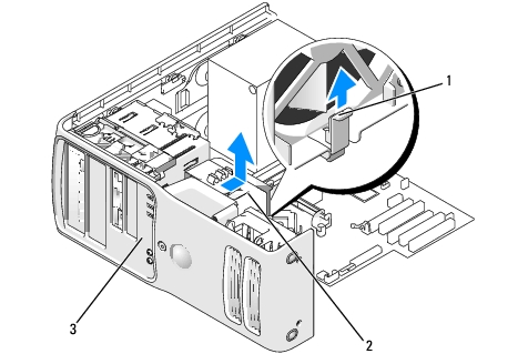
1 |
heat sink and fan shroud assembly |
|
2 |
captive screw housing (2) |
|
3 |
drive panel |
Follow the removal procedure in reverse order, ensuring that the tabs on the top panel, bottom panel, and front panel are secure.
|
|
CAUTION: Before you begin any of the procedures in this section, follow the safety instructions in the Product Information Guide. |
|
|
NOTICE: To prevent static damage to components inside your computer, discharge static electricity from your body before you touch any of your computer's electronic components. You can do so by touching an unpainted metal surface on the computer. |
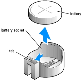
A coin-cell battery maintains computer configuration, date, and time information. The battery can last several years.
If you have to repeatedly reset time and date information after you have turned on the computer, replace the battery.
|
|
CAUTION: A new battery can explode if it is incorrectly installed. Replace the battery only with the same or equivalent type recommended by the manufacturer. Discard used batteries according to the manufacturer's instructions. |
To replace the battery:
|
|
NOTICE: If you pry the battery out of its socket with a blunt object, be careful not to touch the system board with the object. Ensure that the object is inserted between the battery and the socket before you attempt to pry out the battery. Otherwise, you may damage the system board by prying off the socket or by breaking circuit traces on the system board. |
|
|
NOTICE: To connect a network cable, first plug the cable into the network port or device and then plug it into the computer. |
|
|
CAUTION: For instructions about how to safely dispose of a battery, see your Product Information Guide. |
|
|
CAUTION: To guard against electrical shock, always unplug your computer from the electrical outlet before opening the cover. |
|
|
NOTICE: Before touching anything inside your computer, ground yourself by touching an unpainted metal surface, such as the metal at the back of the computer. While you work, periodically touch an unpainted metal surface to dissipate any static electricity that could harm internal components. |
|
|
NOTICE: To disconnect a network cable, first unplug the cable from your computer and then unplug it from the network port or device. |
|
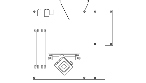
1 |
system board |
|
2 |
screws (10) |
|
|
NOTICE: To connect a network cable, first plug the cable into the network port or device and then plug the cable into the computer. |
