 Front View of the Computer
Dell™ Dimension™ 9150 Service Manual
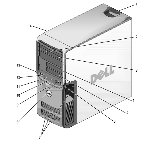
1 cover latch release Use this latch to remove the cover. See "Removing the Computer Cover." 2 CD or DVD activity light The drive light is on when the computer reads data from the CD or DVD drive. 3 CD or DVD eject button Press to eject a disc from the CD or DVD drive. 4 Floppy drive bay Can contain an optional floppy drive. 5 FlexBay Can contain an optional floppy drive or optional Media Card Reader. 6 IEEE 1394 connector (optional) Use the optional IEEE 1394 connector for high-speed data devices such as digital video cameras and external storage devices. 7 vents For adequate cooling, do not block any of the vents. NOTICE: Do not use the vents as handles; doing so may result in damage to your computer. Also, ensure that there is a minimum of two inches of space between all vents and any object near these vents. 8 USB 2.0 connectors (2) Use the front USB connectors for devices that you connect occasionally, such as joysticks or cameras. It is recommended that you use the back USB connectors for devices that typically remain connected, such as printers, keyboards, and mice, or for bootable USB devices, which may not function properly if attached to the front connectors. 9 power button Press to turn on the computer. NOTICE: To avoid losing data, do not use the power button to turn off the computer. Instead, perform an operating system shutdown. 10 hard-drive activity light The hard drive activity light is on when the computer reads data from or writes data to the hard drive. The light might also be on when a device such as a CD player is operating. 11 diagnostic lights (4) Use the lights to help you troubleshoot a computer problem based on the diagnostic code. For more information, see "Diagnostic Lights." 12 headphone connector Use the headphone connector to attach headphones. 13 microphone connector Use the microphone connector to attach a personal computer microphone for voice or musical input into a sound or telephony program. 14 Service Tag Used to identify your computer when you access the Dell Support website or call technical support.
|
1 |
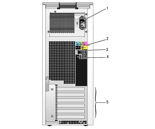
power connector |
Insert the power cable. |
|
2 |
sound card connectors (5) |
|
|
3 |
network connector |
To attach your computer to a network or broadband device, connect one end of a network cable to either a network port or your network or broadband device. Connect the other end of the network cable to the network connector on your computer. A click indicates that the network cable has been securely attached. NOTE: Do not plug a telephone cable into the network connector. On computers with a network connector card, use the connector on the card. |
|
4 |
USB 2.0 connectors (5) |
Use the back USB connectors for devices that typically remain connected, such as printers, keyboards, and mice, or for bootable USB devices which may not function properly if attached to the front connectors (see "System Setup" for more information on booting to a USB device) It is recommended that you use the front USB connectors for devices that you connect occasionally, such as joysticks or cameras. |
|
5 |
card slots (6) |
Access connectors for any installed PCI or PCI Express cards. |