The aim of this Demonstrator is
- to explore the possibility of using ATLAS Online Software(SW) Framework for the TGC Elec. Slice Test in 2002,
- verification of the VMEbus communication using SBS Bit3 PCI-VMEbus adaptor,
- and understanding of ATLAS Online SW Framework.
- Hardware(HW) Configuration
- Run Control PC : PC/Linux(RedHat 6.1, Kernel 2.2.12)
- ROD Controller : PC/Linux(Laser5 6.2, Kernel 2.2.14) and Bit3
- ROD Emulator : PC/Linux(Slackware7.0, Kernel 2.2.13) and Bit3, Memory Module, I/O Module
- SW Configuration
- Online Software : 0.0.14
- Bit3 Device Driver : vmehb-2.2.7
- vmelib : coded by Yoshiji Yasu

The ConfDBs[1] are used by the run control component to define the hierarchy of controllers used in a partition and determine which programs need to be started and stopped.[2]
In this demonstrator, ConfDB consists of three parts which are based on Online Software Exercise[3].
The tgc_demo.data.xml file describes the partition which defines all components, including SW and HW, and configuration of DAQ System.
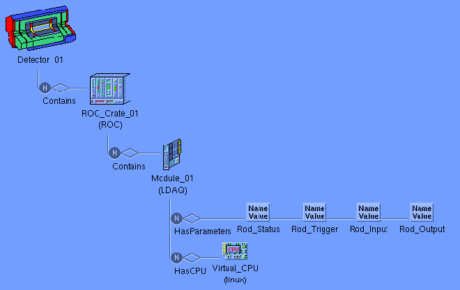
The tgc_demo.hw.data.xml file describes a Detector, a ROD Crate and a ROD Module. And the ROD module has four parameters(ROD_Status, ROD_Trigger, ROD_Input, ROD_Output).
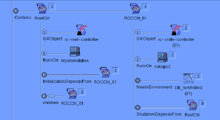
The tgc_demo.sw.data.xml file describes software configuration in terms of run control applications.

In the ATLAS Online SW, the controllers are organized into a hierarchical tree structure that reflects the general organization of the experiment itself. The hierarchy is defined in the ConfDB. Each controller in the tree can have one parent controller and any number of child controllers. At run-time, the controllers read the confDB to retrieve their own parameters and discover who are their children. At the top of the tree is a single controller which represents the overall state of the entire system. The hierarchical tree of controllers transmit messages between themselves to exchange commands and status information.[2]
There are two Controllers in the demonstrator that is, ROOT Controller and ROD Crate Controller(ROD CC). The ROOT Controller(named "RootCtrl") we use "rc_root_ctrl" program which is included Run Control Package of Online SW. The ROD CC(named "ROCCtrl_01") we use "crate_controller" program which is included Exercise Package of Online SW. The "rc_root_ctrl" program runs on Control PC and the "crate_controller" runs on another PC which emulates ROD CC. And we use another PC which emulates ROD module. (See Fig. 1 and Fig. 3)

The ROD CC receives commands from the ROOT Controller running on the control PC and
communicates to the ROD module via VMEbus.
The following actions, matching the run control finite-state machine[2], have been implemented:
- Load :
- Read the ROD Crate and ROD Module Information(VME address, Parameters of the Module) from ConfDB.
- Initialize ROD Emulator running on another PC using Remote Shell(temporary way).
- Config:
- Set ROD_Status bit "1" on the VME Memory Module. This means ROD Module is alive.
- Set ROD_Trigger bit "0" on the VME Memory Module. This means ROD Module is disable.
- Make a crate IS Information available and send a message when going to configured state.
- Start:
- Set ROD_Trigger bit "1" on the VME Memory Module. This means ROD Module is enable. The ROD Emulator program, which was started by RSH, begins to count up the it's Counter. And it writes the Counter's value to memory of VME MEM Module.
- "crate_controller" read the Parameters from MEM Module via VMEbus. And it updates the value of parameters to inform the GUI Panel using IS information.
- Stop:
- Set ROD_Trigger bit "0" on the VME Memory Module. This means ROD Module is disable.
- Pause:
- Set ROD_Trigger bit "0" on the VME Memory Module. This means ROD Module is disable.
- Resume:
- Set ROD_Trigger bit "1" on the VME Memory Module. This means ROD Module is enable.
- Reset:
- Set ROD_Trigger bit "0" on the VME Memory Module. This means ROD Module is disable.
- Set ROD_Status bit "0" on the VME Memory Module. This means ROD Module is dead.
- Set ROD_Input value "0" on the VME Memory Module.
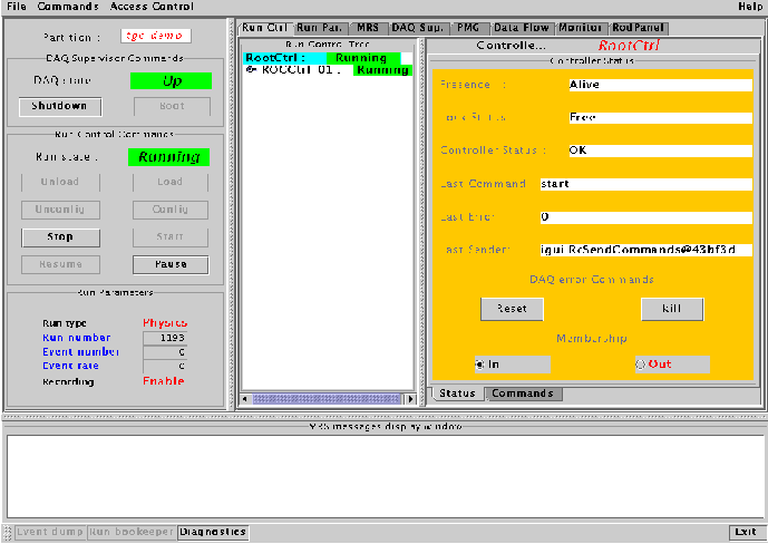
- Run Control Panel
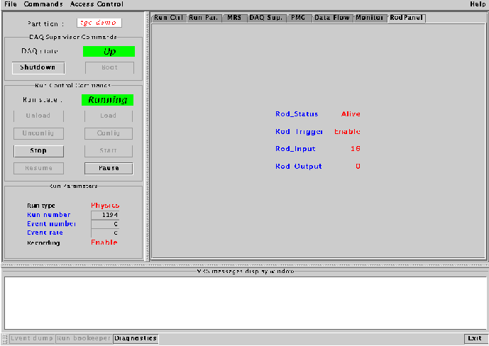
- ROD Panel
IGUI(Integrated Graphical User Interface) is one of the software components of the Online SW. IGUI is intend to give a view of status of the data acquisition system and its sub-systems and to allow the user to control its operation.
IGUI is a Java application(JFrame). On the left side of the frame are displayed the Main Commands and below are some major Run Parameters, such as run and event number. On the right side there are different Panels which can be chosen by clicking the corresponding tab buttons.

ROD Panel shows the ROD parameters, defined in the ConfDB and updates at regular intervals.

Communication between ROD CC and Rod-Panel, we use the same scheme as Exercise Package[3] of Online SW in this Demonstrator. That is we use IS Information to communicate between ROD CC and Rod Panel. Fig. 4 shows ROD parameters on the ROD Panel. These Parameters defined in the ConfDB are updated by ROD CC at regular intervals(a few seconds).
In this Demonstrator ROD Emulator is very simple. The ROD Emulator is consists of three parts: PC - Bit3 VME adaptor, VME Memory Module and VME I/O module. Also the software of ROD emulation is very simple. The ROD emulation software has a "couter", "ROD Input", "ROD Output", "ROD Trigger Enable" and "ROD Status". If the "Trigger Enable" is "1", the "counter" in the ROD Emulator counts up itself and writes counter's value to the "ROD Input". If the "Trigger Enable" is "0", the "counter" stops counting.